Friday, 11 December 2009
Sunday, 6 December 2009
Sunday, 29 November 2009
Friday, 27 November 2009
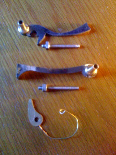
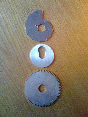
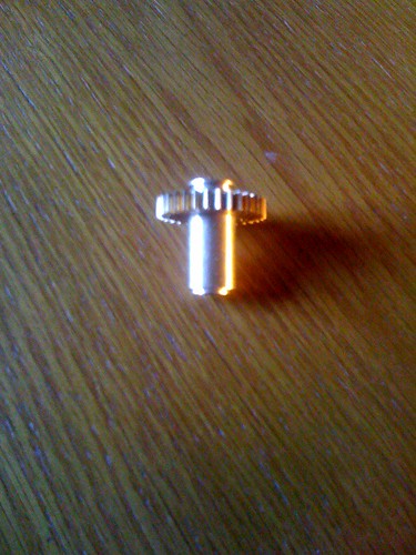
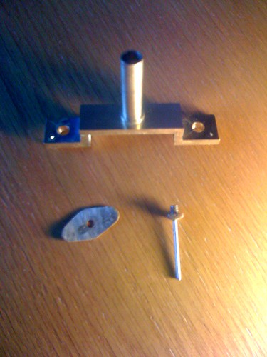
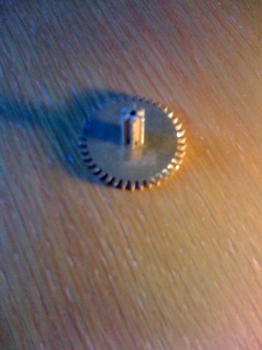
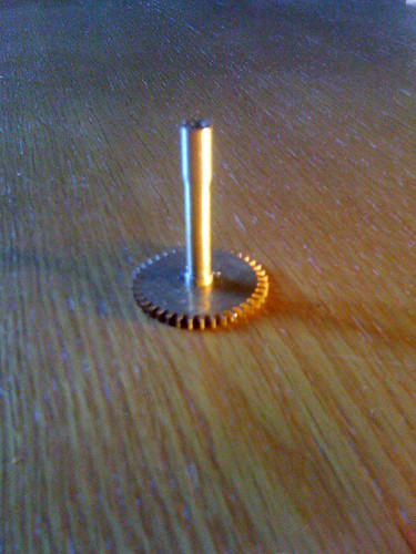
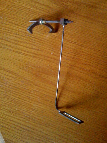
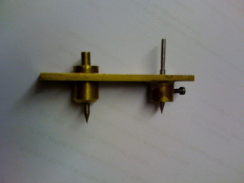
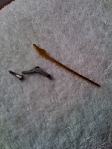
pallet arbor crutch
The 1/8" arbor goes all the way through a hole drilled through the centre of a 1/4" mild steel block. The crutch is 1/16" steel rod soldered to the block. The slotted plate is milled from 1/16" mild steel.
I round the inside edges of the slot to stop it snagging on the suspension spring block.
I round the inside edges of the slot to stop it snagging on the suspension spring block.
Thursday, 26 November 2009
Saturday, 21 November 2009
Tuesday, 17 November 2009
Next:
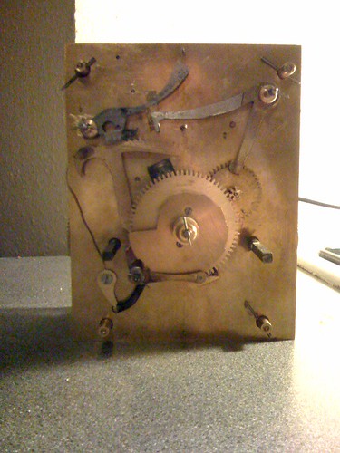
Next I would like to make the pallet arbor crutch. But this can't be fitted until I cut out the top slot in the back plate. Because once it's soldered on I won't be able to get it out unless that slot is cut. But; one of my registering pins is right there in the way, and I need it to help me position and depth the striking train. So the striking train has to be done next all the way up to the fly. Then I can cut out the back plate, so that I can work down towards the pendulum.
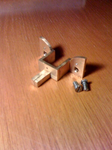
The Backcock
Two pieces of brass angle 3/4" x 3/4" x 1/8"
A piece of brass strip 1/2" x 1/8" and a piece of 1/4" brass rod.
Silver soldered together and milled square.
The 1/4" square piece is riveted on by turning a spigot on the end. Cut a slit in the square rod on the milling machine.
When in position correctly clamp it down and spot through the two 2BA and two register pin holes.
Sunday, 15 November 2009
Saturday, 14 November 2009
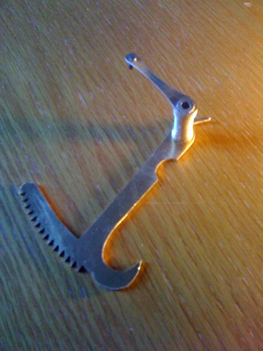
Making the Anchor
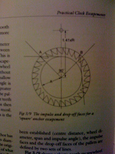
To mark out the steel for the anchor I either clamp the scape wheel directly to the high carbon steel sheet or mark it on paper then scribe from that. This Escapement is a square recoil escapement, square because the pallets span 7 1/2 teeth of the scape wheel which has 30 teeth.
So mark (on the paper) the 7 1/2 points (with a dot of your pen)
Coincidentaly (and this is not critical) the inner circle of your crossed out wheel is approximately right for finding the degree of angle for the two impulse faces (radius= .71). So scribe/draw a line from your dots and across the inner circle so it just touches it, one across the top from the left pallet and one down the right from the right pallet. Next put in the drop-off face angles; from the centre of the wheel draw a line outwards directly to both dots and past, shade in to make clear this is metal to keep.
Next find the position for the anchor arbor. The distance between the arbors is X.
X divided by the radius = 1.41 ~ so the radius multiplied by 1.41 = X.
In this case 1.15.
Use a compass to scribe this line, it doesn't matter too much where along the anchor the arbor hole goes. Place it centrally to look good.
Carve all this out of the steel keeping clear of the scribe lines as it can be shaped little by little in the depthing gauge. Hopefully it should jam as you have made it too big and when it is nearly there finish it off by planting it in the clock. When it is nearly there remember to file/polish down the drop-off faces which shortens the pallet instead of taking too much off the impulse faces making it 'drop' too far.
Friday, 6 November 2009
Saturday, 31 October 2009
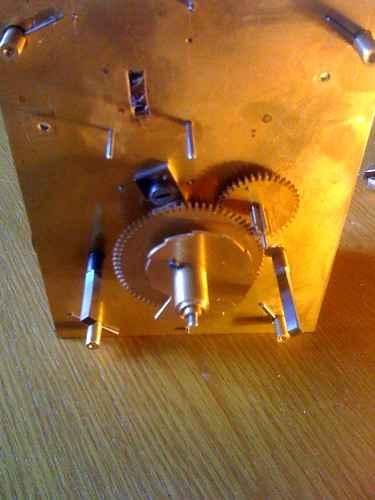
Mounting the Great wheels and going train.
Disassemble the chassis and put the two plates together in the register pins. Scribe out the positions for the great wheel arbors, at 2 1/4" from the bottom and 1 9/16" either side of the centre line. Drill and ream to fit.
Next depth the 96tooth great wheel to the centre wheel pinion on a simple homemade depthing tool. Scribe an arc across the centre line, drill and broach. Then depth the centre wheel to the Scape pinion and scribe that arc which will be 2 1/16" furthur up the plate.
Next depth the 96tooth great wheel to the centre wheel pinion on a simple homemade depthing tool. Scribe an arc across the centre line, drill and broach. Then depth the centre wheel to the Scape pinion and scribe that arc which will be 2 1/16" furthur up the plate.

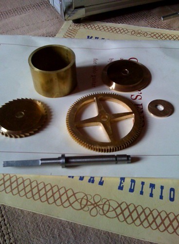
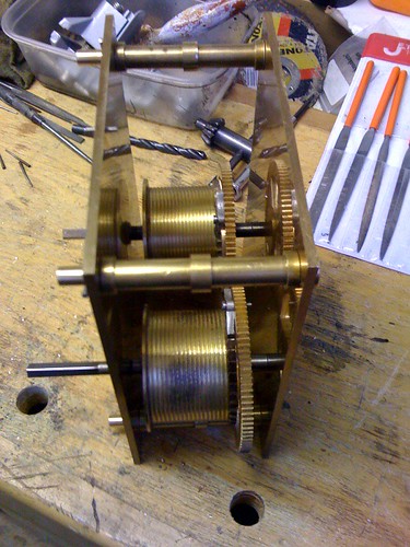
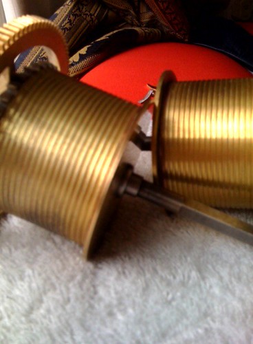
Barrels, end plates, slip washers and ratchets.
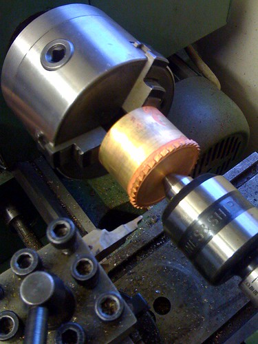
For the barrels I used 2" drawn brass tube. 1 3/8" long. Faced off nicely in the three jaw chuck.
The four endplates are out of 3/16" sheet. All the centres are drilled and reamed to the 5/16" for the arbors. Two of them will be the ratchets and are turned down to 2 1/8" dia. The other two are 2 1/4 dia with a spigot turned to fit the barrel by using a mandrel in a collet. A spigot is also turned on the ratchet ends only 1/32".
Next I groove/screw cut the barrels. Silver solder on the endplate, mount it back on the mandrel with the tailstock applying pressure in the endplate hole.
Set the lathe up to do 14 threads per inch and take very light cuts remembering backlash so you have to come out furthur (towards the tailstock) to keep on track.
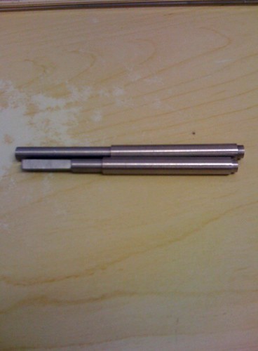
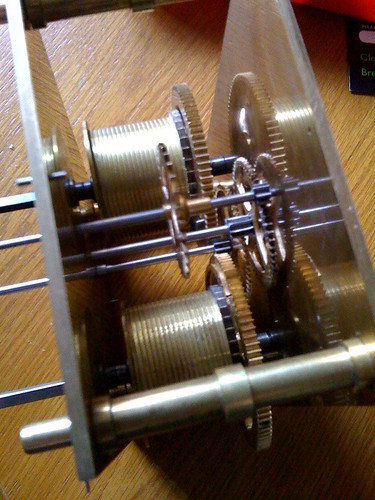
Barrel Arbors
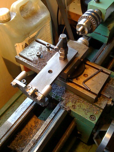
My barrel arbors are machined from 5/16" dia silver steel. Again I fabricate. Each about 5" long I turn down the small spigot 1/8" at 1/4" dia. Then the other end I turn down 1 1/2" to 1/4 dia.
Then I make some steel shoulders. (note: make them extra large so its not too fiddly to braze. They can always be turned smaller later)
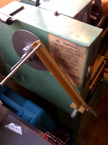
A groove needs to be cut with the parting-off tool for the slip washer. It's all not too critical as the shoulder will soldered after the barrel, ratchet and endplate is mounted. Then I square off 7/8" in a 'roller filing rest' in the lathe, using a division plate giving me four quarters. (pics attached).
Then I make some steel shoulders. (note: make them extra large so its not too fiddly to braze. They can always be turned smaller later)
A groove needs to be cut with the parting-off tool for the slip washer. It's all not too critical as the shoulder will soldered after the barrel, ratchet and endplate is mounted. Then I square off 7/8" in a 'roller filing rest' in the lathe, using a division plate giving me four quarters. (pics attached).
Thursday, 29 October 2009
pinions
Here I make pinion wire. All of my pinions are made out of 5/16" diameter stock on the milling machine. When I have cut all my leaves I can cut off a pinion one at a time at the required length, drill the hole and position on the arbor. A main advantage of fabricating instead of turning the whole arbor & pinion from solid is so that it is much easier to depth the pinions to the wheels using a simple homemade depthing tool. 3 pinions are to have 8 leaves and 4 have 7.
The 3rd and Centre pinions are 8 leaves and both are turned down to the 3/16" to hold their wheels respectively. The Scape, Fly, Warn, and Pallet are 7 leaves. And the Pin is 8 leaves. Pinions and pivots should be hardened and tempered to prevent wear.
The 3rd and Centre pinions are 8 leaves and both are turned down to the 3/16" to hold their wheels respectively. The Scape, Fly, Warn, and Pallet are 7 leaves. And the Pin is 8 leaves. Pinions and pivots should be hardened and tempered to prevent wear.
Saturday, 24 October 2009
collets
Five wheel collets are to be made to hold four wheels and the anchor. The other wheels are held by the pinions turned down to make shoulders. The center holes are 1/8" the spigot is 3/16 so we can use 3/8" rod for this procedure.
Friday, 23 October 2009
Cutting the teeth.
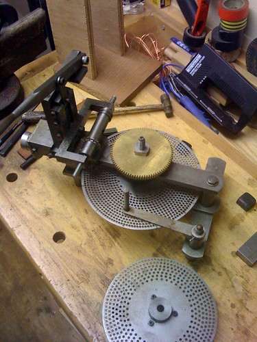
I use a homemade 'wheel cutting engine' to cut my teeth. But the milling machine can be used to do this as well as the lathe can- with a milling head. If preparation and planning is all sorted then all the teeth of the wheels can be cut in an evening.
Make a mandrel: use 1/2" steel rod, turn down one end to the 3/16ths for your wheels. Then thread the end 2 B.A. with a washer and nut to hold the work tight.
Mount your mandrel in a horizontal holder on the machine table with the applicable division plate attached at it's other end.
Centre up your 0.8 module cutter by using a lathe centre point.
The Wheels
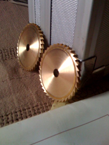
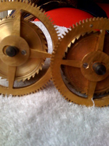
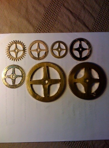
Seven wheels are cut out of 1/16" Compo brass sheet with a bandsaw. Then turned down to exact measurements on the lathe. The Centre will have 60 teeth and is 1.975" Diameter. 3rd has 56 teeth at 1.849" Dia. Also the Pin wheel has 56 teeth at 1.849" Dia. The Scape has 30 teeth at 1.650" The Pallet has 49 teeth at 1.628", the Warn has 42 at 1.408" the Hour has 72 teeth at 2.353".
There are then two Minute wheels (one for going in reverse) made out of 3/32" material. They have 39 teeth at 1.313" Diameters.
The Centre, 3rd, Pin, Pallet and Warn are pierced out with a jewellers/piercing saw. to have four crossings/spokes each. You can saw and file this to taste bearing in mind the centre bore hole is 3/16", and the Pin wheel has extra 'meat' to house the pins for the Bell hammer tail.
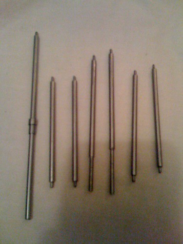
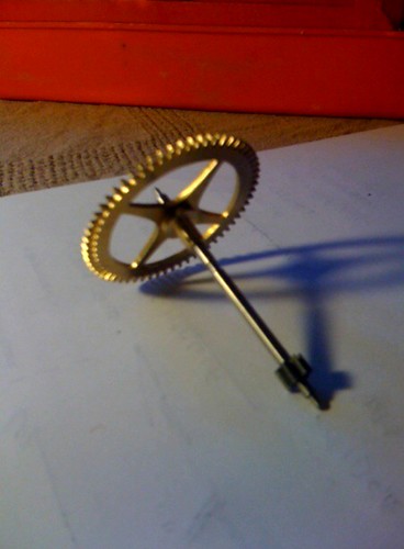
Arbors
Next is the arbors. Seven. (not including Barrel arbors). The 'Going' gear train runs on three arbors. The Scape, the 3rd, and the Centre. One end of the Scape arbor protrudes through the front plate 7/8" for the seconds hand, and one end of the Centre arbor protrudes through 1 7/8" for the minute hand. A shoulder will need to be made to hold the centre arbor in place (also to carry a wheel) as it's full width passes through the front plate.
The striking gear train - Fly arbor, Warn arbor, Pallet arbot, and Pin arbor. The fly, warn and pin are made the same as the 3rd arbor of the going train. Make them loose fitting (endshake) by offering them up to the chassis for a feel. Turn the pivots to .060 .
The Pallet arbor protrudes through the front plate 7/16".
Thursday, 22 October 2009
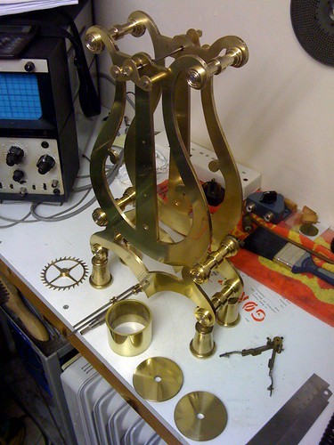
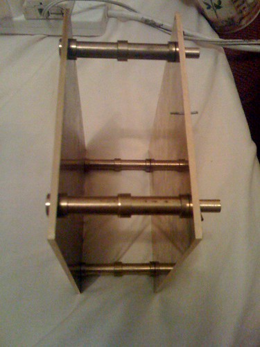
the chassis
After a few evenings I have my chassis assembled tight.
I milled square, two pieces of engraving brass - 5" x 6 3/8".
I found the centre datum line and 'registered' the plates together using small taper pins.
The pillars are 3" long and have a spigot both ends.
One spigot gets faced off for a 4 B.A tapped hole, the other gets rounded off for 'quick release' taper pins. Each pillar is made for each hole respectively, I give a small, hidden mark to signify pillars l, ll, lll, and lV.
Spot through the plates with a centre bit then clamp it all down real tight to stop it grabbing as the pillar-drill pops through.
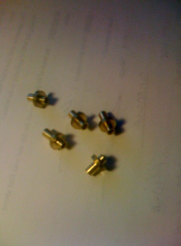
I've made rings to decorate the pillars.
I made the steel screws and brass washers.
I milled square, two pieces of engraving brass - 5" x 6 3/8".
I found the centre datum line and 'registered' the plates together using small taper pins.
The pillars are 3" long and have a spigot both ends.
One spigot gets faced off for a 4 B.A tapped hole, the other gets rounded off for 'quick release' taper pins. Each pillar is made for each hole respectively, I give a small, hidden mark to signify pillars l, ll, lll, and lV.
Spot through the plates with a centre bit then clamp it all down real tight to stop it grabbing as the pillar-drill pops through.
I've made rings to decorate the pillars.
I made the steel screws and brass washers.
Sunday, 18 October 2009
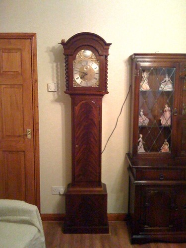
In the beginning
On this blog I intend to proceed step by step on how to make a grandfather/longcase clock. It will be in the style of a traditional English clock circa the 17th century. Few of the methods and techniques are of recent design, like using modern adhesives and using fabrication techniques here and there.
I feel it perfectly reasonable to allow a flexibility in ones own project and the freedom to explore alternative methods if one wishes. Because I feel sure if the clocksmiths of yesteryear could, they would most certainly take advantage of the modern materials and ideas of our 21st century.
So here goes; how to make a 17th C longcase clock with a few 21st C methods.
Subscribe to:
Comments (Atom)
